Interface

Machine Vision Camera Interface

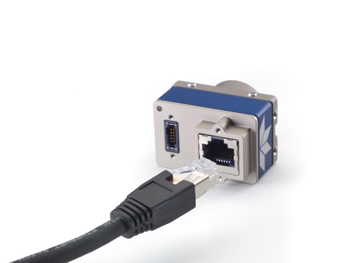
Machine vision cameras are used in a variety of applications, including semiconductors, electronics, biotechnology, assembly, and manufacturing industries. The best camera system for the task at hand is crucial to achieving the best image quality. Digital cameras are available with a variety of interface options that are often dependent on an application’s requirements. Some formats, such as the USB varieties, can greatly simplify the setup process by supplying video output and power via a single interface. Other formats may require an additional power supply but provide advantages such as higher data transfer rates, which affects the camera’s framerate, or support for a greater number of simultaneous devices. The following table compares the different digital camera interfaces: 

Digital Interface Data Transfer Rate Max Cable Length # Devices Connector Capture Board 
USB 3.1 5Gb/s 3m (recommended) up to 127 USB 3.1 Micro B/USB-C Optional 
GigE (PoE) 1000 Mb/s 100m Unlimited RJ45 / Cat5e or 6 Not Required 
5 GigE (PoE) 5Gb/s 100m Unlimited RJ45 / Cat5e or 6 Not Required 
10 GigE (PoE) 10Gb/s 100m Unlimited Cat7 or Optical Cabling Not Required 
CoaXPress up to 12.5Gb/s >100m at 3.125Gb/s Unlimited RG59 / RG6 / RG11 Optional 
Camera Link® up to 6.8Gb/s 10m 26pin Required 
USB 3.1 Gen 1 is a popular interface due to its ubiquity among computers. It is high speed and convenient; maximum attainable speed depends upon the number of USB peripheral components, as the transfer rate of the bus is fixed at 5 Gb/s. Gigabit Ethernet (GigE) and 10Gigabit Ethernet (10GigE) are other popular interfaces. CoaXPress and Camera Link® are dedicated machine vision interfaces typically used in such applications. In addition to the cameras, systems using these interfaces require frame grabbers. These are specialized adapter cards to receive image data and assemble it into usable images. 

Please note that the choice of interface depends on your specific application needs, including factors like bandwidth, cable length, power delivery, system cost, and ease of integration.

  • FireWire (IEEE1394b): This interface, which is declining in use, has a bandwidth of 80 MB/s and a cable length of 4.5 m. It has low CPU usage and excellent support for multiple cameras. 
  • Gigabit Ethernet (GigE): Widely used GigE has a bandwidth of 125 MB/s and a cable length of 100 m. It has medium CPU usage and good support for multiple cameras.
  • USB 3.1: This increasingly used interface has a bandwidth of 400 MB/s and a cable length of 3 m. It has low CPU usage and excellent support for multiple cameras.
  • Camera Link: Camera Link was Launched in 2000 by Automated Imaging Association (AIA). CameraLink has been upgraded progressively, and now has an HS version, to support higher data speeds, with some versions requiring two cables for transmission.
  • CoaXPress (CXP): Launched in 2008, CXP interfaces use 75ohm coaxial cables and support data transfer speeds of up to 6.25Gbit/s per channel, with the ability to use multiple channels to support even faster data transfer rates.
Uncategorized

Military, Machine Vision Interfaces Converge to Mutual Benefit.

Great Article discussing how the military is taking advantage of machine vision technologies.  Dr. Lee at Pyramid Imaging contributed to the content.

by Winn Hardin, contributing editor – AIA

On land, sea, and air, imaging systems are helping military organizations with surveillance and situational awareness improve their performance in tasks critical to command, control, communications, computers, intelligence, surveillance, and reconnaissance (CR4ISR).

Standards such as GigEVision, Genicam, and CoaXpress (CXP) are bringing unique benefits in image data delivery and compatibility, helping to keep warriors safe while reducing the cost of upgrading militaries to the newest technologies.

“In the past, most applications were point to point,” says Harry Page, President of Pleora Technologies Inc. “There are a wide range of predominantly proprietary approaches to support point to point applications, but increasingly the demand from end-users is for a standards-based networked approach to multicast video and data from multiple endpoints to processing, recording, and display units. This is resulting in a split in the military market.

“On one side, incumbent suppliers want to continue to introduce new, and often still proprietary point-to-point solutions that they completely control. It’s basically a land grab for these manufacturers, because once they sell a system, they get to support that system for many years. This approach is increasingly at odds with users, who want open architectures, commercial technologies, and networked solutions that meet real-time latency demands while delivering and multicasting sensor data across multiple systems.”

Polaris’ new MRZR-X illustrates this point. The MRZR X is a finalist in the U.S. Army’s unmanned equipment transport vehicle program. The vehicle can transport or support a squad while driving autonomously. According to Patrick Weldon, Director of Advanced Technology at Polaris, his company is adopting an open-architecture model to help speed the introduction of technology to the troops.

“The squad is now the best source of information in combat,” Weldon said, and an open architecture approach will help get that technology and information there.

Vision Standards for Mobile Military Platforms

According to Pleora’s recent white paper, Local Situational Awareness Design and Military and Machine Vision Standards, the features and capabilities of GigEVision and GeniCam align well with the requirements of emerging military vehicle data standards, such as those from the British Ministry of Defense (MoD) Vetronics Infrastructure for Video over Ethernet (VIVOE) Defence Standard (Def Stan 00-82) and the U.S. Department of Defense Vehicular Integration for C4ISR/EW Interoperability (VICTORY) initiative.

Pleora’s Page acknowledges that open standards-based network architectures potentially pose cybersecurity concerns compared to single-point solutions. However, he says “…instead of critical subsystems with a single point of failure, what we suggest is that every camera should be accessible through a service-oriented architecture. Through software, you can then define the video distribution services both inside and outside the vehicle.”

Moving from single point to an imaging network will help military vehicles handle the size, weight, and power (SWaP) challenges of even the largest battle tanks with heavy power requirements for electronic systems. When you add the redundancy of a network architecture, expandability, scalability, upgradeability, and the ability to integrate with other networked C4ISR subsystems, Pleora’s Page asserts that the efficiencies and increased operational effectiveness offset the security concerns, while freeing up resources for improving cybersecurity.

CXP and surveillance

While coaxial cable can be found in mobile platforms in addition to land-based platforms, the requirements for CXP “on the move” are different.

“A number of our frame grabbers have been used in drones,” says Keith Russell, President of Euresys, Inc., a manufacturer and supplier of image acquisition and processing components for machine vision and video surveillance applications. “[The military] choose CXP because of its low latency and the need for an autonomous drone and our support of ARM architectures for processing the visible and thermal imagery using low-power ARM processors.…

“[But] one of the things behind CXP is the large analog infrastructure that uses coaxial cable in military installations. And in many cases, multiple sensors will transport along that cable and CXP uses multiplexing to manage multiple data streams over a single channel.”

Bandwidth is another area where CXP can trump GigEVision networks, according to Dr. Rex Lee of Pyramid Imaging Inc. “The government still wants to use commercial off the shelf [COTS] wherever they can,” says Dr. Lee. “When we look at the components we sell into military applications between GigE, CXP and Camera Link, etc., it is about the same as the industrial side of our business.

“Basically, military customers only want to pay for what they need. So, if they need more bandwidth, CXP, which requires a frame grabber, can be a better solution than GigEVision, which doesn’t require a frame grabber. Or, in the case of 360-degree surveillance systems with slip ring and power supply, CXP-to-camera direct connections can have a lot of benefits. A single conductor with slip ring allows for cost-effective 360-degree surveillance using pan, tilt, zoom, and it only needs one cable.

“For applications that require 360-degree continuous surveillance, such as situational awareness applications for forward operating bases that identify nearby enemies by muzzle flares, high-resolution, high-speed cameras are a necessity. Pyramid Imaging’s embedded processing capabilities within smart cameras allow dramatic bandwidth reduction. Thus GigE Vision or single coax CXP can be used, offering much lower system costs,” concludes Dr. Lee.

As machine vision enables more machines to see and respond to their surroundings, managing imaging network data along with size, weight and power becomes more important to advanced mobile platforms. And it’s not just for the military. The same imaging adoption and need for network and power management are also attracting the attention of the consumer automotive market.

“The technical challenges of real-time video and data sharing for autonomous cars and military vehicles are very similar, but the markets are moving at a different pace,” says Ed Goffin, Marketing Manager at Pleora. “The military market made a concerted effort to standardize image networking for vehicles, and as a result there are now systems in the final stages of testing or early deployment. Some of the ‘lessons learned’ from the military market around standards, networking, processing, and maybe most important human usability should play a key factor in the ongoing evolution of autonomous car technologies.”

Industrial Lenses

Whats all the buzz about Liquid Tunable Lenses?

The technology is based on the principle of a shape-changing lens.  Consisting of a container filled with optical fluid and then sealed off with an elastic polymer membrane.  When an electromagnetic actuator is used to exert pressure on the container holding the fluid, a deflection of the lens occurs.  The resulting effect is the focal length of the lens is then controlled by the current flowing through the coil of the actuator.  The relationship between the current and the optical power, which in the inverse of focal length, is linear.

Tunable lenses are designed to deflect in a positive direction, which means that the actuator pushes towards the membrane.  In early development, to achieve negative optical power, a plano-concave offset lens was added.  Today’s tunable lenses now have the actuator bonded to the membrane and is able to pull the membrane away from the container with negative currents, which result in a concave lens shape.

The membrane thickness influences the tuning range of the lens, thinner membranes, achieve a larger range of optical power due to the reduced restoring force.  The refractive power of the lens can be changed by using different optical fluids with different indexes of of refraction.

For machine vision applications the benefits of using liquid tunable lenses are:

  • Greater working distance
  • Faster responseFocus Tunable Lenses
  • Reduced lighting requirements
  • Easy to install and use

Optotune, based in Switzerland, recommends using a tunable lens in 3 configurations:

  • Front- Lens, mounted on filter thread of a fixed focus lens you can achieve working distances from infinity to 100mm. This is the most versatile configuration.
  • Back-Lens configuration – the tunable now lens acts as a distance ring when placed between the caemra and a fixed focus lens, providing an easy mechanical solution.  This configuration will provide the best quality for short working distances.
  • High magnification or Telecentric  – here the tunable lens is placed between the tube lens and the zoom lens and is best for high magnification applications.  This configuration works best with infinity corrected lenses and achieves up to 100x magnification.

Excellent applications for a front lens configuration is Bar Code reading, Robotic Vision, package sorting and bottle inspection. Back lens configuration is an excellent choice for C-mount macro imaging applications and works with lenses at a focal length >=35mm.  Other applications for back lens configuration is Electronic inspection, laser processing, contact lens inspection and diamond inspection.  High magnification/telecentric applications benefit from a tunable lens by increasing the Z-range and optimizing  a telecentric lens for large format imaging.  Recommended applications for this use of a tunable lens is in, camera phone lens inspection, IC inspection, LCD & PCB inspection and particle counting in liquids.

This is a high level over view of the technology and where it may best be applied.  For more information on tunable lenses, or to discuss your application please give us a call at 813-984-0125 or email Sales@pyramidimaging.com.  You can also explore tunable lenses on our website at, Optotune lenses at PyramidImaging.com.  Content courtesy of Optotune.


Camera Link · CoaXPress · Range Extenders

Extending your Vision – How Range Extenders are adding value to High Speed Machine Vision Applications

Over the last 18 years, options for acquiring and analyzing images has increased dramatically.  Today’s choices include Camera Link, CoaXpress, Camera Link HS, USB (2 and 3), GigE Vision, 10 GigE and the newer Thunderbolt I/O.  However, limits exist for all these technologies with regards to cable length and bandwidth.  These limits create challenges for even the most experienced machine vision application engineer.

Camera Link and CoaXPress are highly recommended for high speed events.  Camera Link (now at version 2.0) is still a go to standard, with a maximum distance of 10 meters and a payload throughput of 850 MB/s it was built for real time, high bandwidth communication.  Buyers of Camera Link have plenty of options when it comes to the cameras, as well as all the connected devices that use the Camera Link standard (as of the last posting, 84 manufacturers have licensed Camera Link products).   The newer, CoaXpress standard was introduced by the Japan Industrial Imaging Association in 2009 and in cooperation with other interested parties maintain the standards.  CoaXpress offers users up to 6250 Mb/s of data transfer at 40 meters and 1250 MB at 130 meters which is more robust, although there are less than 10 manufacturers of CoaXPress cameras, supported devices such as Frame Grabbers and cables are well represented in the industry.

With the limits on distance and bandwidth, Camera Link and CoaXPress posed design challenges as the cameras had to be closer to the objects being captured and recorded.  Technology introduced in 2016 allows extending the range and maintains the high quality, high speed imaging for which standards are known.

Leading the way in these technologies, Kaya Instruments based in Israel has introduced extenders for both Camera Link and CoaXPress.  Constructed of two converters, one on the camera side and one on the Camera Link/CoaXPress frame grabber side, these devices provide bidirectional communication over fiber.  The camera link extender offers 10.3125 Gbps equal to Camera Link Full/80 bit (Deca) over a single fiber cable. The CoaXPress extender introduced in 2017, increases the standard CoaXPress transmission distances yet maintains the low jitter, low latency and high resolution CoaXPress delivers.  The extender enables video, control signals and power over CoaXPress (PoCXP) transmission for full control of data stream and camera handling. The CoaXPress range extender can provide a downlink of up to 6.25Gbps and uplink at 20.83Mbps.  Other options from Kaya Instruments include; CoaXPress over Coax, Single Link CoaXPress. Additionally, acquisition systems for both Camera Link and CoaXPress provide the extended distances and increases data transfer rates using interface boards with the extender.  Starting at around $1,500 these devices will expand Camera Link and CoaXPress capabilities making these standards a solid go to solution for high speed, high bandwidth, extended distance applications.

Other manufacturers are also recognizing the need to extend the range of Camera Link and CoaXPress.  Manufacturers Phrontier Technologies, SkyBlue, and Vivid Engineering are just a few who have solutions available.

So, don’t let the limit of the standard hold you back, these relatively low-cost devices can Extend your Vision.  If you are facing a challenging vision project, give us a call or email us at sales@pyramidimaging.com.  With 20 years of experience in machine vision, we have most likely already solved your challenge.  Machine vision is touching every industry and solving real world problems, can’t wait to see where you all take it next.

machine vision

Cost Drivers and other considerations for a successful machine or embedded vision project

Cameras typically take up the lion share of revenue resources in a machine vision system; however, today’s cameras are faster, smaller, lighter, smarter and less expensive. A good quality GigE monochrome camera should cost an end user around 1K, costs will go up as megapixel size increases. 

genie-nano Euro block IO cable straight

When choosing a camera interface keep these points in mind: 

  • GigE Vision: Used in low & mid-end vision systems with less critical speed and timing demands; cost effective solution when full speed is not required. 
  • Camera Link: Industry default choice for higher speed connectivity where limited cable length and high cable costs are acceptable, frame grabber is required 
  • CoaXPress: Newer technology, for applications that require higher speeds, longer cable lengths, a frame grabber is required. 
  • Camera Link HS: Originally designed to overcome the speed limitations of Camera Link for line scan cameras, frame grabber will be required 
  • GigE Vision over 10 GigE:  Built on GigE Vision, faster physical layer and better timing accuracy with much higher power consumption; requires server grade equipment for implementation. 


Depending on the camera and the method in which you wish to obtain or retain the data from the image, a Frame Grabber may be required (see camera interface information above).  Frame Grabbers come in a variety of configurations; choices include; bandwidth and DDR-RAM size, on-board camera controls, the number of cameras that each board controls and the newest innovation adds FPGA programing on the board. A basic frame grabber will cost around $500.00, a frame grabber with FPGA programming capability will run around $2,500 or more depending on the configuration of the board, but keep in mind, the board with FPGA will allow you to reduce your CPU/GPU requirements as your images will now be preprocessed. Using an FPGA enabled frame grabber will likely reduce costs for computer related hardware as your bandwidth and RAM requirements will be much less than with a traditional Frame Grabber.   

Depending on your application, lighting can be a strong contender for vision system dollars.  Good lighting is essential to the success of a machine vision system.  Most vision applications will benefit from line lights or back lights.  Getting the lighting right will save you development dollars.   A good quality 5” line light or backlight can run $450-$850 depending intensity controls and size.  Ask your machine vision expert of integrator about how best to “highlight” your intended object. 

Lenses typically represent the lowest percent of dollars spent on a machine vision system.  A standard machine vision 16mm lens typically runs $100-$200, but a high quality specialty lens, such as motorized or Near IR corrected can run well over $1,000.00.  Be sure to invest in a good quality lens. 

Software can be free when the SDK (software development Kit) from the camera manufacturer is included in the camera purchase or can run thousands when complex licensing schema or specialty vision software is required.  There are many machine vision related software solutions on the market, make sure your machine vision professional explains what the free SDK can do for you before investing in costly software. 

Cables represent the least costly part of a vision system but be sure to get certified cables from a reputable cable manufacturer and ensure your integrator is not cutting corners by using cables made by non-certified manufacturers.  A bad cable can make a great vision system worthless. 

Imaging is now touching every industry, entertainment, marketing, auto, aerospace, packaging etc.  Just think of all those robots being developed!  The newest technology is the “Smart” camera.  These cameras have embedded FPGA software right on the board and can be addressed using flow chart style programming.  No longer will vision engineers need an FPGA programmer to complete the system, with a little training a vision engineer will be able to program camera controls, enhance images and much more, all from their desk top or mobile device.  It is truly an exciting time to be involved in machine and embedded vision. 

If you need more information or assistance with a current of future project please contact us at sales@pyramidimaging.com.  And please, visit our website we are working hard to make it informative and easy to use.  


Filters

Imaging Problem? A Band Pass filter might be your answer.

MidOpt_Choosing_a_Filter-Imaging Problem? A Band Pass filter might be your answer. To find the right filter for the job, a broad spectrum white light and a bandpass filter kit will help you highlight various wavelengths. During testing each bandpass filter will achieve similar results as the matching LED wavelength. This process will help you to determine the appropriate LED wavelength necessary for your vision application. By viewing each resulting image each banpass provides, you can determine the best color for maximizing contrast and reduce interfering light. Your vision system may also benefit from other filters to help reduce glare, remove saturation or balance color.
For more in depth information on filter use for your vision system, visit this article link from Mid West Optical, More Info

If you need additional assistance or you need to add a filter swatch kit or specific filters to your image lab please reach out to us at Contact Us

Cameras

Understanding Back Illuminated Technology in machine vision

Until Hideo Yamanaka published his 2009  “Method and apparatus for producing ultra-thin semiconductor chip and method and apparatus for producing ultra-thin back-illuminated solid state image pick up device”.  The technology of back illuminating sensors was costly, complex and required further refinement to become a widely used sensor.  Yamanaka found that by rearrangement of the imaging elements, increased light could be captured and thereby improve low-light performance.  However, back thinning lead to a host of other problems such as cross-talk which causes noise, dark current and color missing between adjacent pixels.  Thinning also made the silicon wafer more fragile.

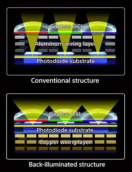
A traditional front illuminated camera is constructed to mimic the human eye; a lens at the front and photodetectors at the back, a back illuminated sensor arranges the wiring behind the photodiode substrate layer by flipping the silicon wafer and then thinning its reverse side so that light can strike the photodiode layer without passing through the wiring layer.

Front vs Back Illuminated CMOS

Front illuminated CMOS sensors vs. Back Illuminated CMOS.

Today back illumination technology has made some significant progress and BI chips are now available from several manufactures of Silicon Chip technology.  With higher sensitivity over a broader spectral region (deep UV to near IR) several industrial camera manufacturers are introducing back illuminated cameras.

These cameras are ideal for ultra-low light applications like Astronomy, Spectroscopy and biological imaging.  With back illumination, low light applications get increased Quantum Efficiency up to 95% and lower read noise at <2 e-rms.  When every photon counts a camera with a back illuminated sensor should be your one and only choice.

If interested in incorporating a back illuminated camera into your project check out the new .pco Panda 4.2 BI :  PCO. Panda 4.2 BI


Cameras

5 Reasons You Should Choose a 10 GigE Camera for your Machine Vision Application.

There are many types of Ethernet cameras available for machine vision applications. This is a brief introduction to Ethernet and why 10GigE cameras are attractive. Continue reading “5 Reasons You Should Choose a 10 GigE Camera for your Machine Vision Application.”

Cameras

What is the Best Machine Vision Camera for my Application?

How to select the right camera for your machine vision application?  I would like to present a brief description of the basic procedures that my company, Pyramid Imaging, uses when asked by our customers to determine the best camera for their application.  We’ve been doing this type of work for decades and have developed a simplified but reliable way to narrow down the broad array of possible cameras to a small group of possible candidates.

But, let’s talk about some basics.  We consider a machine vision camera as a camera that will be used to obtain images for an automated process.  We need a camera that has the right number of features that will allow us to control it properly and obtain the images that we require.

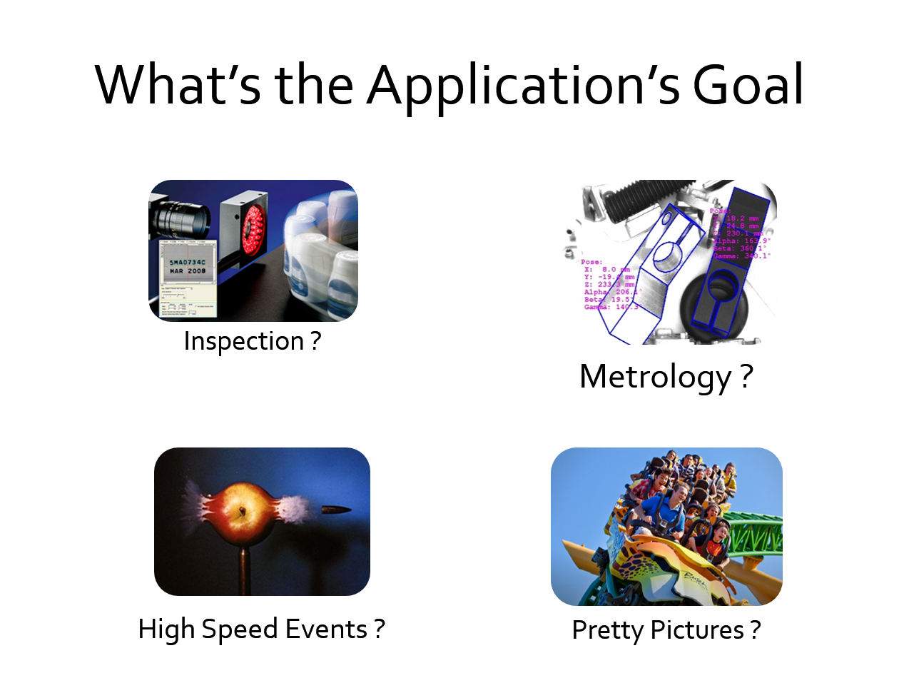
First and foremost is to understand the application’s goals.  Are we looking at an Inspection process looking at labels and barcodes, are we requiring Metrology to be done; that is, making accurate measurements on an item?  Maybe we are examining high speed events or do we just need “pretty pictures” for presentation purposes?

Application Goals

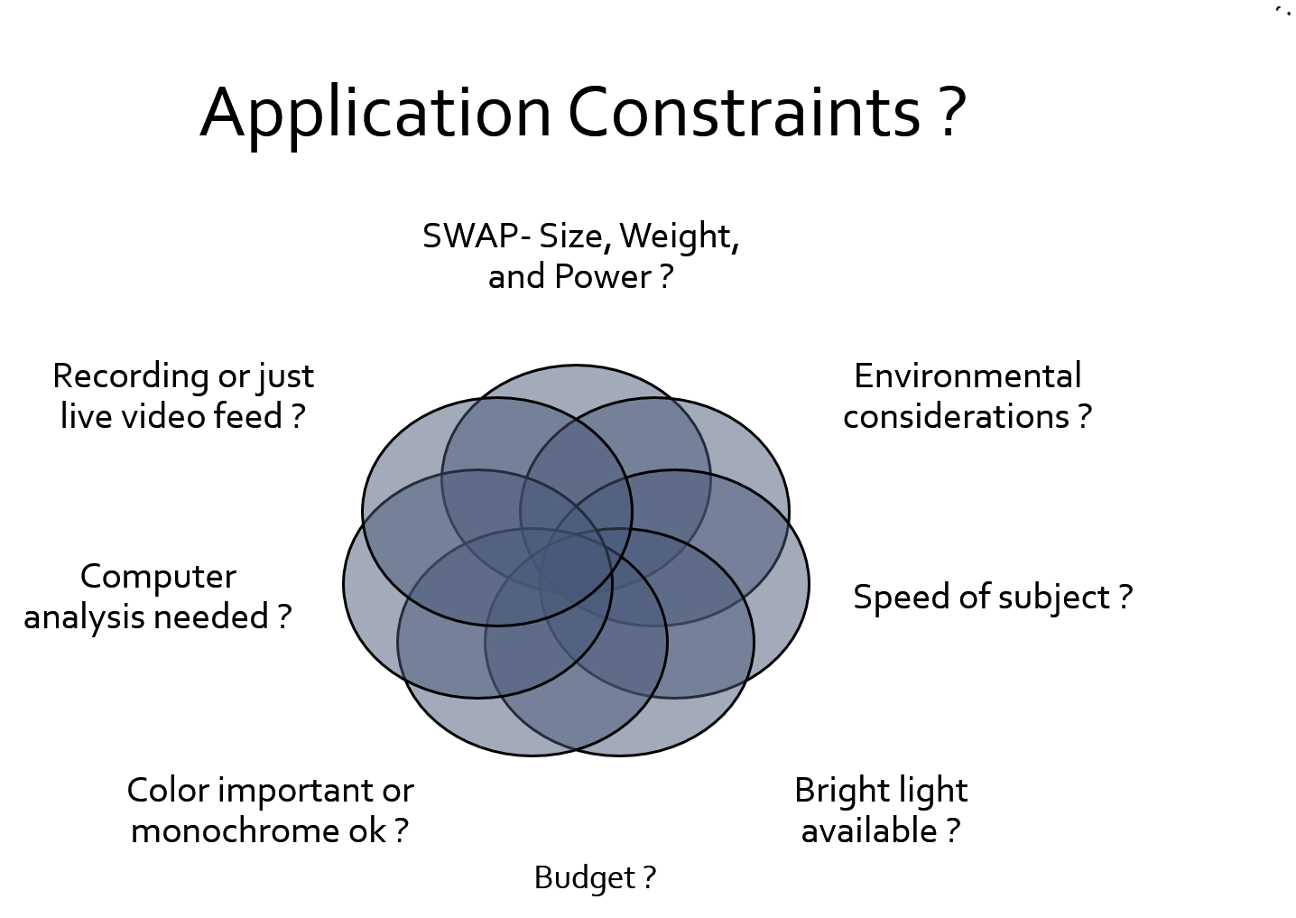
Once we truly understand the goal for using a machine vision camera we need to now list all of the application constraints.   We are now looking for the sweet spot in the constraint analysis in which the best camera will satisfy all the requirements.

Application constraints

There are literally thousands of cameras to down select to the one that will be best for your machine vision application.  The broad categories for these cameras include cameras that are:

  • Line Scan – 16K Linear array
  • Area Array – 80 MP and higher
  • High Speed – hundreds of thousands of frames per second
  • Analog (RS-170), FireWire, USB 3, GigE, Camera Link (CL) , Camera Link HS, CoaXpress

These cameras area all about bandwidth and cable length.  Remember that high resolution and high speed cameras need high bandwidth requirements!

You also need to know what lens mount the camera should possess.  These include:

M12, CS, C, F, M42, M75 Lens Mounts.

These are listed in order of increasing aperture. Remember that the bigger the sensor the larger the camera opening needs to be for a lens with a larger aperture.  Also, note that for a line scan camera using a linear array sensor the sensor’s length would be used to determine the largest image circle needed from a lens.  For an area array camera you would use the diagonal length of the imager.

There are also various features that might be required in a camera.  Features such as:

  • Selectable Regions of interest(ROI)
  • FPGAs
  • On camera memory
  • Many others

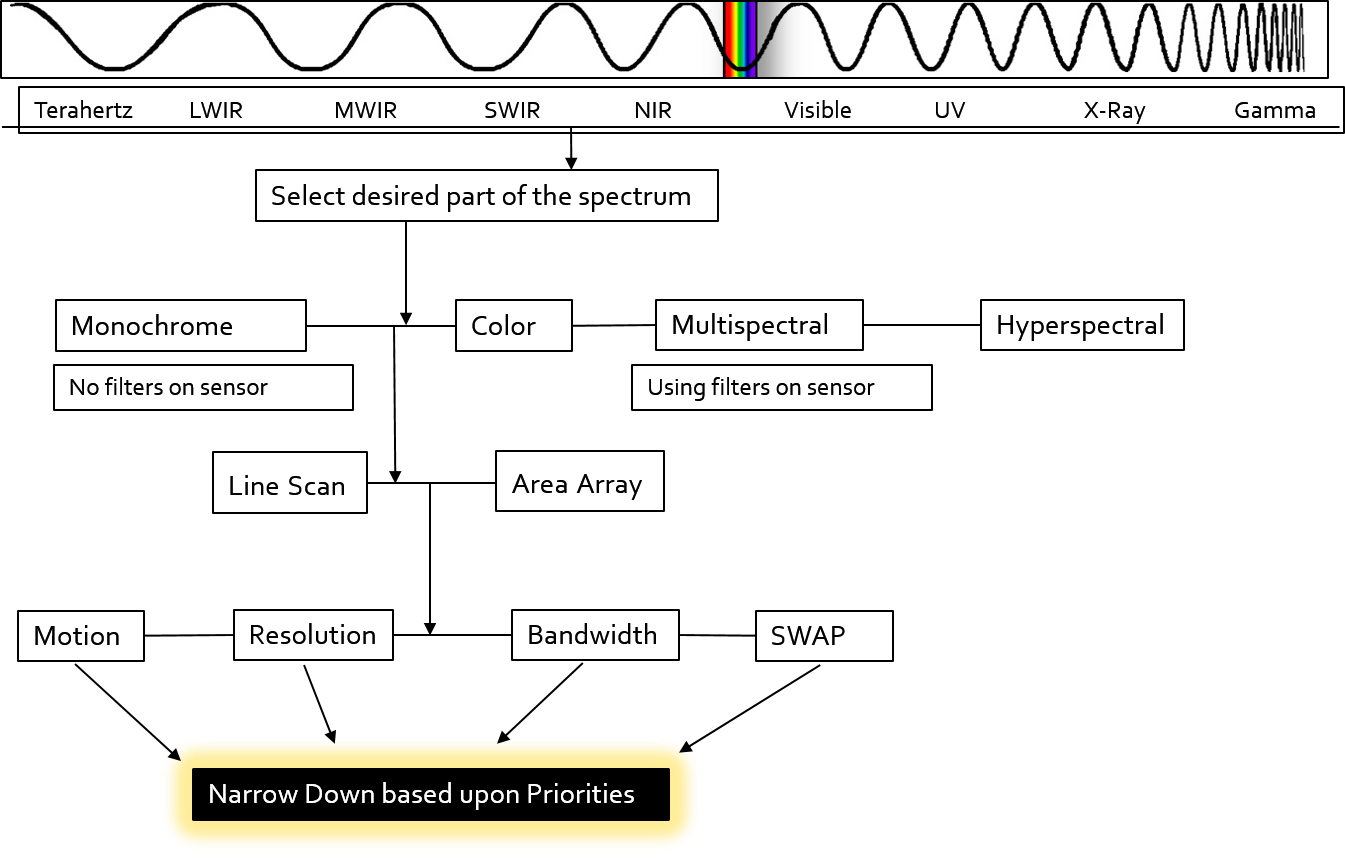
Here is a type of decision tree that can be considered when trying to select the best machine vision camera:

decision tree for camera

There are many factors to consider when trying to select the appropriate and best machine vision camera for your application.  First and foremost you need to analyze and reanalyze the goals for the machine vision application.  The next vital consideration is to use the best lighting and illumination to highlight the objects of interest.  You want to create as much contrast as possible between what you  want to see and try to make everything else disappear.

So, a quick set of steps for selecting the right camera would be to:

  1. Calculate Resolution- smallest detail in the field of view.
  2. Calculate the object or camera speed- determine best exposure time and frame rate to “freeze” the image.
  3. Encoder or speed sensor ?  If yes prefer line scan !
  4. Distance from computer or display ?  Resolution, Frame rate, Distance dictates data bandwidth , video protocol and cables.
  5. Time to record ?  Dictates amount of RAM and/or RAID storage.
  6. SWAP and other constraints ?  Prioritize
  7. Narrow down and sort camera list on priorities- features, cost, lead time, technical support, viability of manufacturer, etc.

Pyramid Imaging has been providing assistance to customers for decades on selecting the right cameras and other machine vision components.  Go here to see a small example of some of the projects in which we’ve been involved.

Pyramid Imaging  provides this very convenient tool that you can use to  down select cameras based upon certain specifications.  Just go to the camera selector and click on the specifications desired.

We’d be happy to provide you with our free assistance should you like to discuss your application with our experts.  Just Contact Us.